Build Your Own 90s Electronic Style Custom Mechanical Keyboard
I have been in contact with the mechanical keyboard customization circle for about a year, and I bought a lot of kits during this period, but most of them can be said to be different. Basically, a template comes out with 68 configurations, 75 configurations, 98 configurations, etc., and you can come back. The basic thing to do is to put the keycap on the upper shaft body, adjust the big keys and other relatively simple things.
It was very fresh at the beginning, and I got tired of playing too much. Later, I accidentally came into contact with the 40% kit of 0xcb static, and then I realized that there is such a thing as an open source project (the 40% kit has no extra PCB on hand, so I will play a few more pieces later. Come back and write another article) After that, I became obsessed with this kind of keyboard production where I found open source projects, printed PCBs, purchased electronic components according to the bom table, and bought the main controller to flash the firmware. Starting from 0xcb static, I found more interesting keyboard open source projects. In fact, the disciphline 65% standard configuration has aroused my great interest.
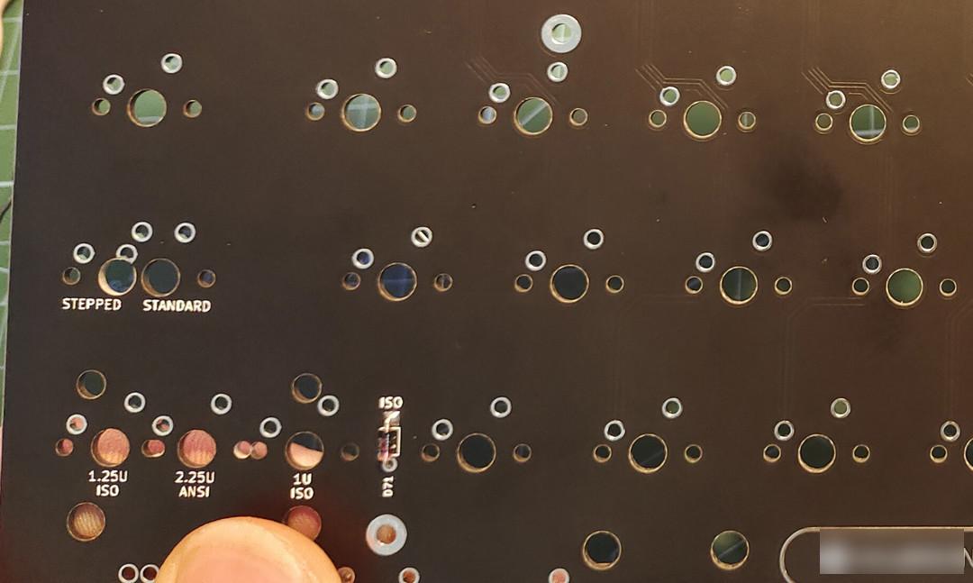
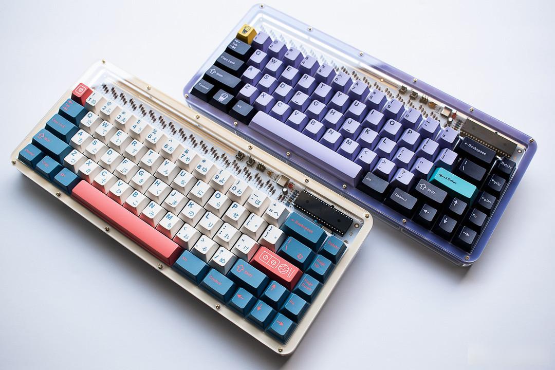 discipline 65%
The same exposed style as 0xcb static diodes, a smell of retro electronics industry blows your face. Basically, many electronic components are the same as above 0xcb static. Seeing the remaining piles of diodes, I immediately decided to print the PCB and buy the main control back. Make a standard keyboard. Relatively speaking, the 68-key keyboard is more versatile and easy to use.
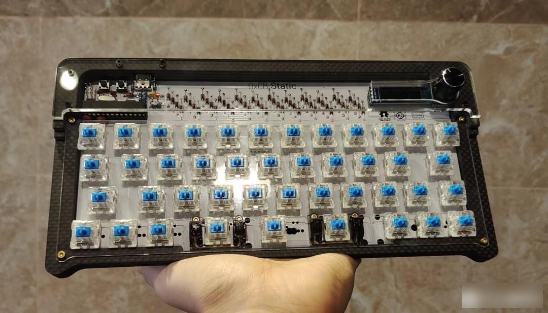 0xcb static 45%
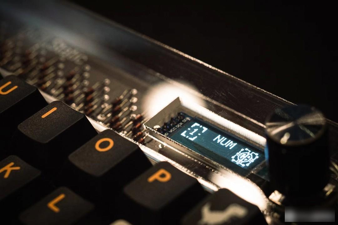 0xcb static also has a small screen
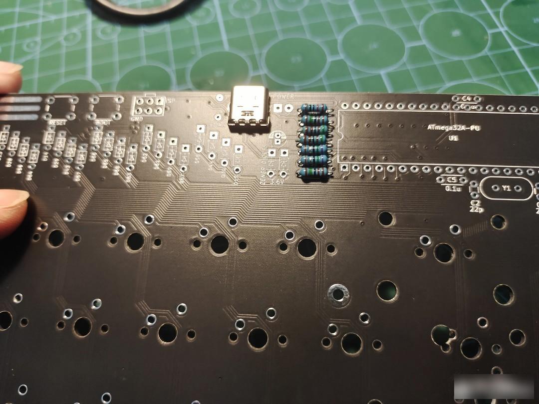
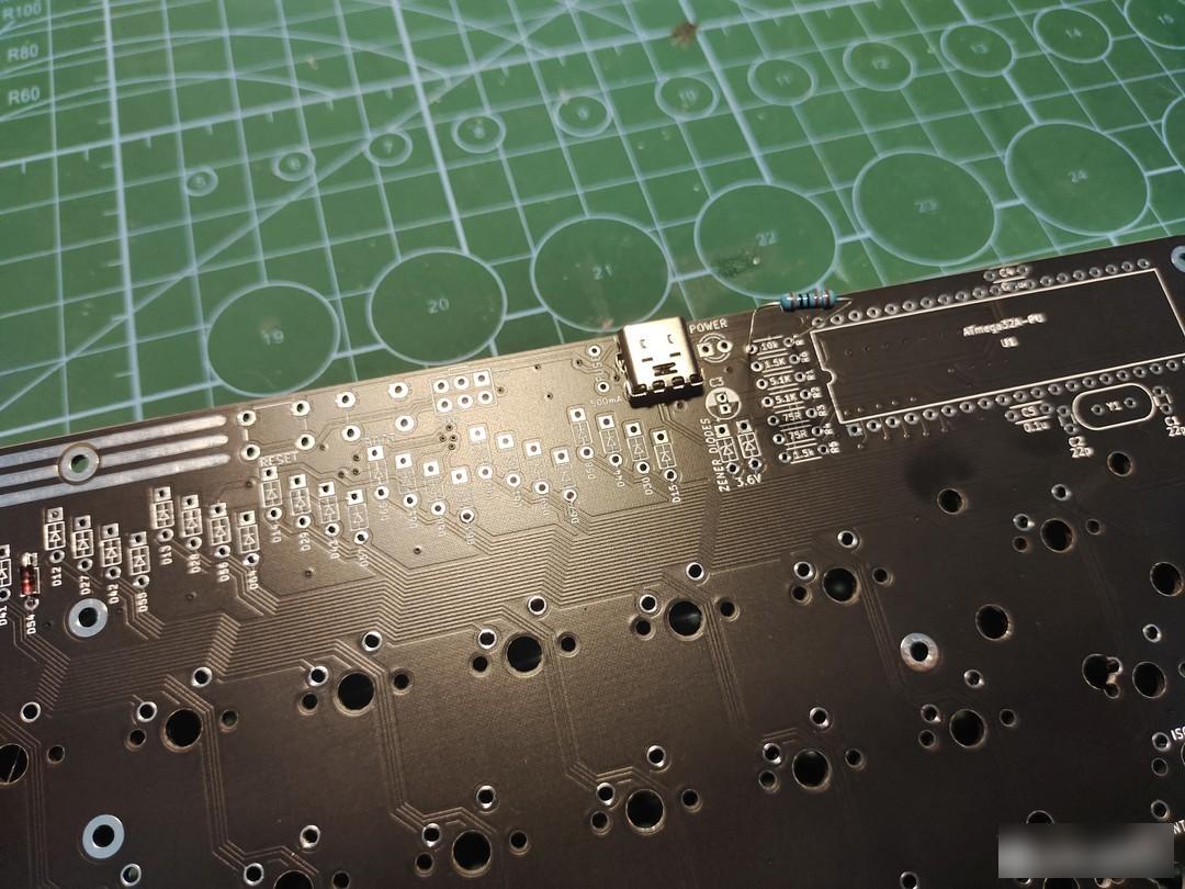 TYPEC and 10K resistors
The first difficulty of plug-in components may be the soldering of the typec interface, but don’t worry, solder paste and air gun can easily solve it. Remember to test the circuit with a multimeter after soldering. Insert the resistors one by one according to the markings on the motherboard, 10K, 1.5K, etc. Regardless of the positive and negative poles, just insert them according to your preference.
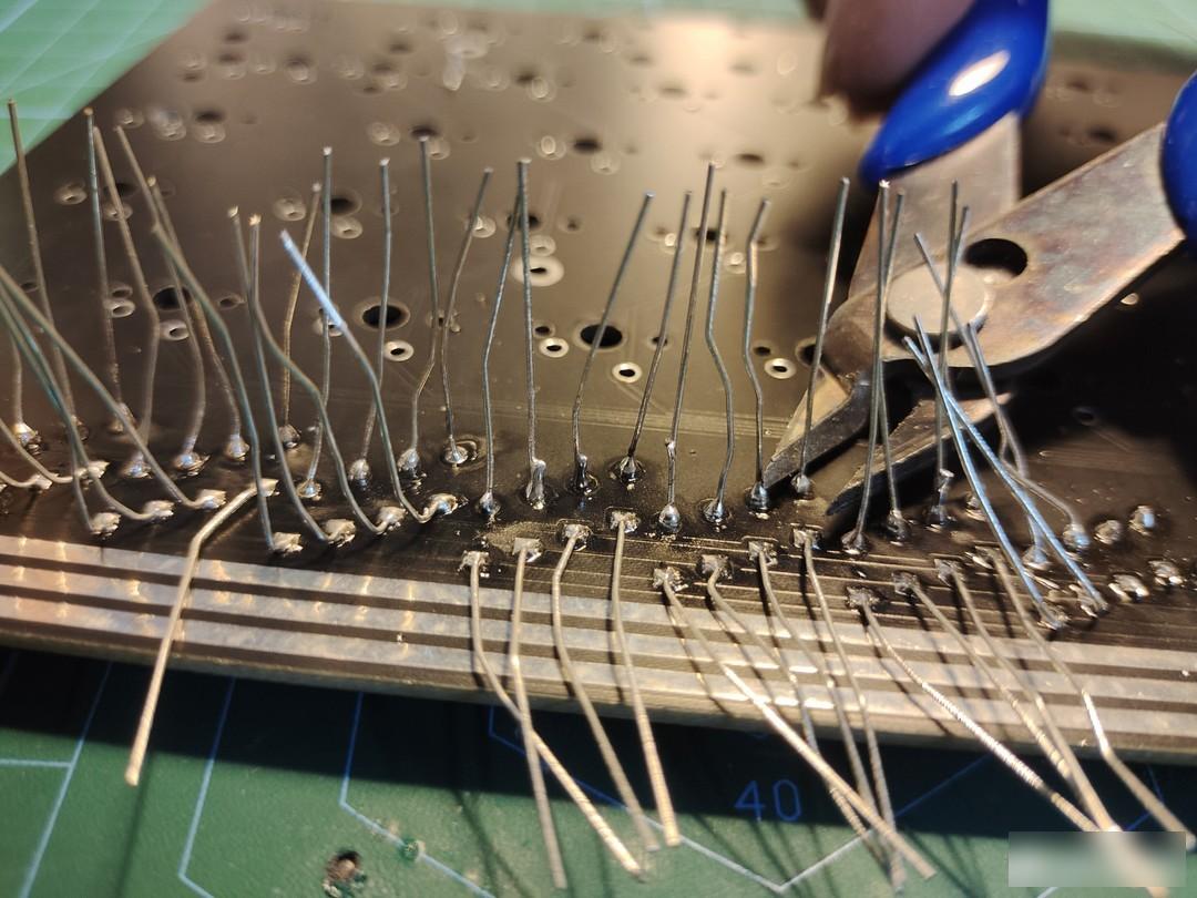
After soldering the tin, you can cut off the excess pins, remember to use better quality solder
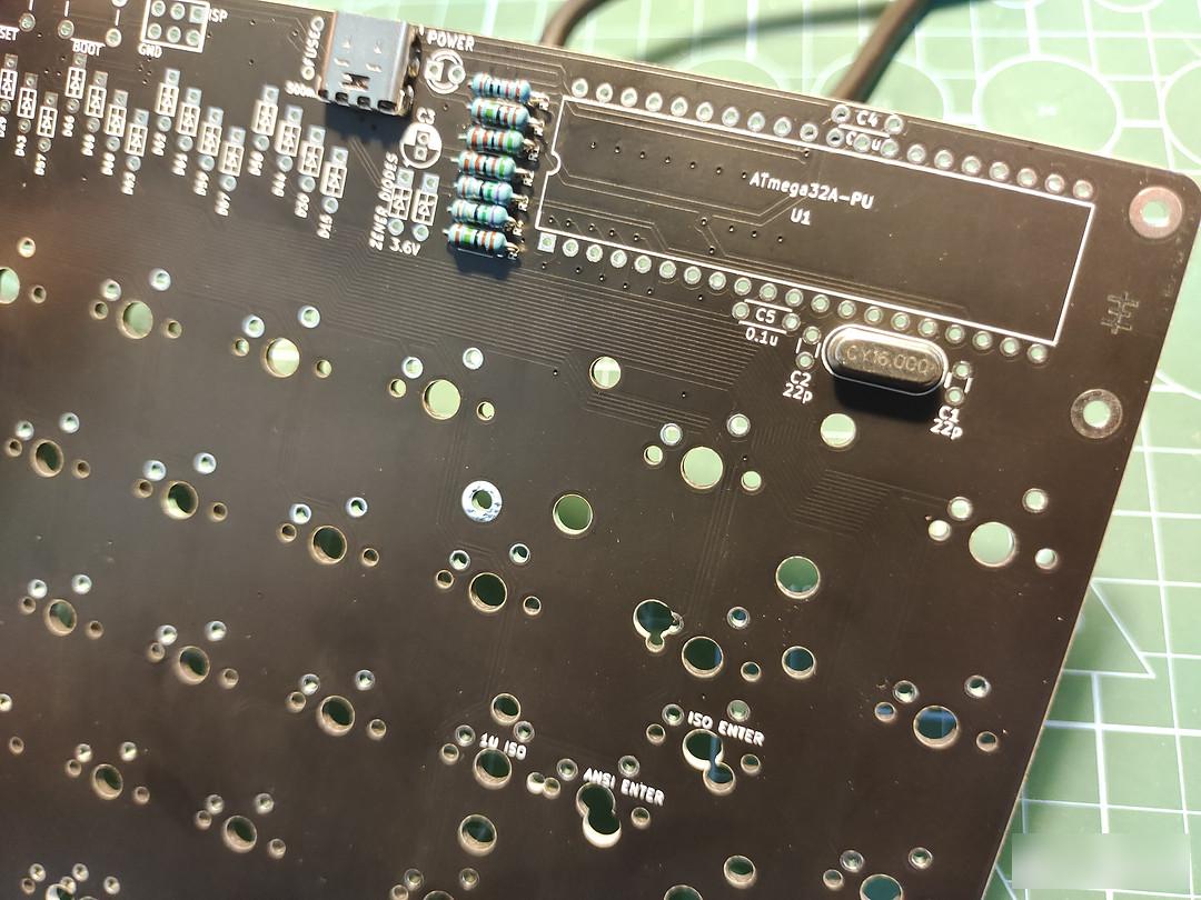
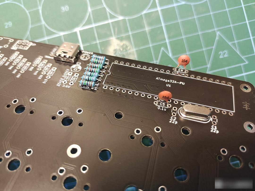
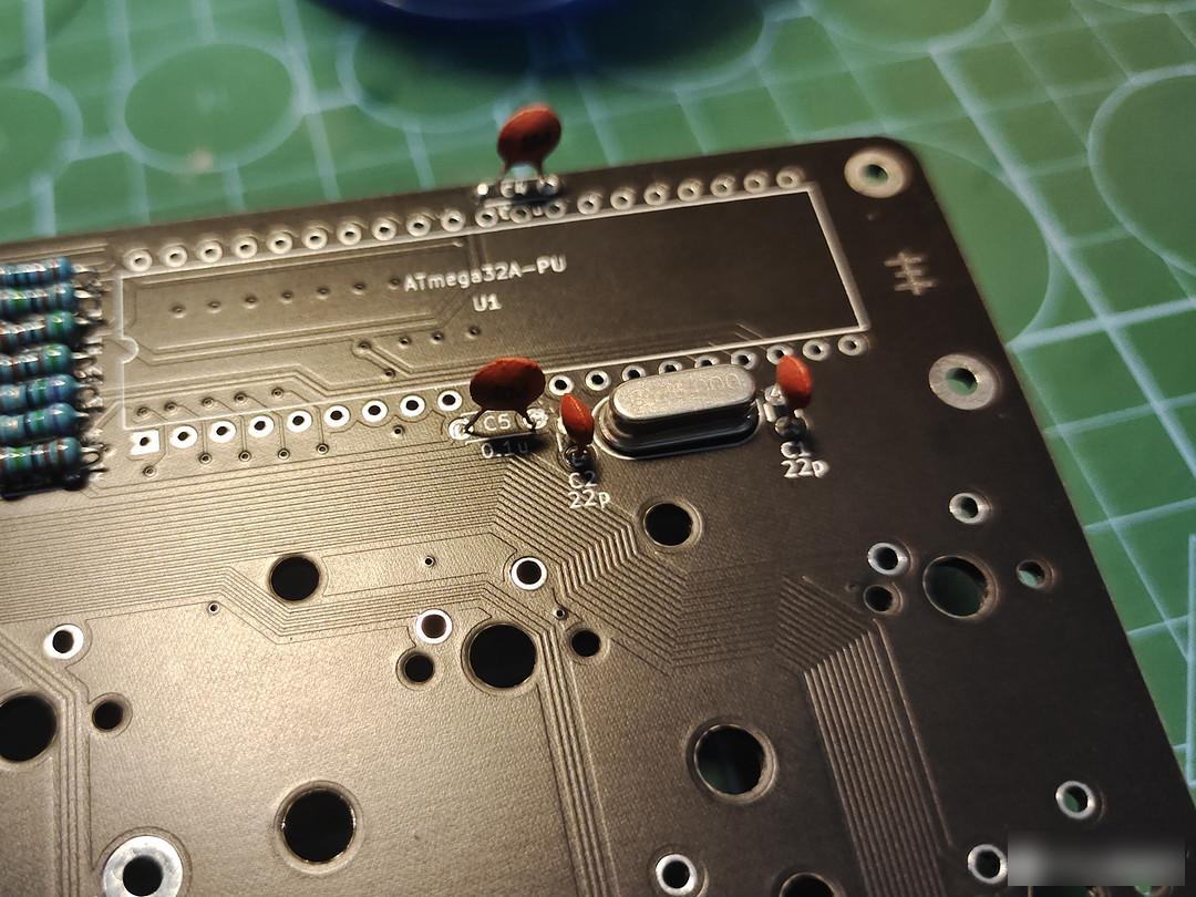
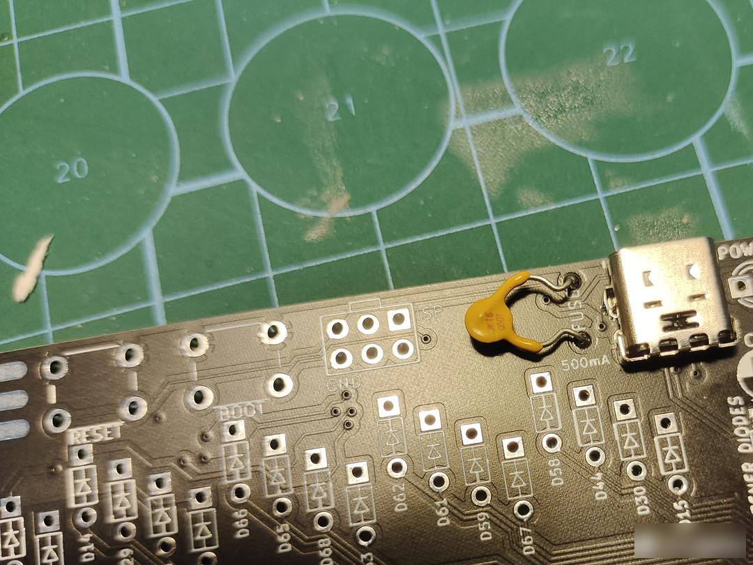
Then there are crystal oscillators, SMD electronic capacitors, and insurance, regardless of positive and negative poles.
The two switches are also connected, although it has little effect temporarily
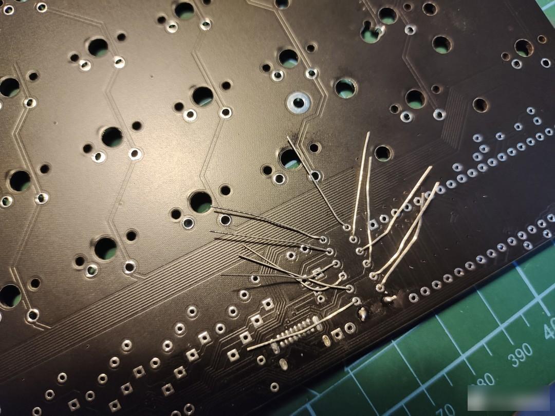
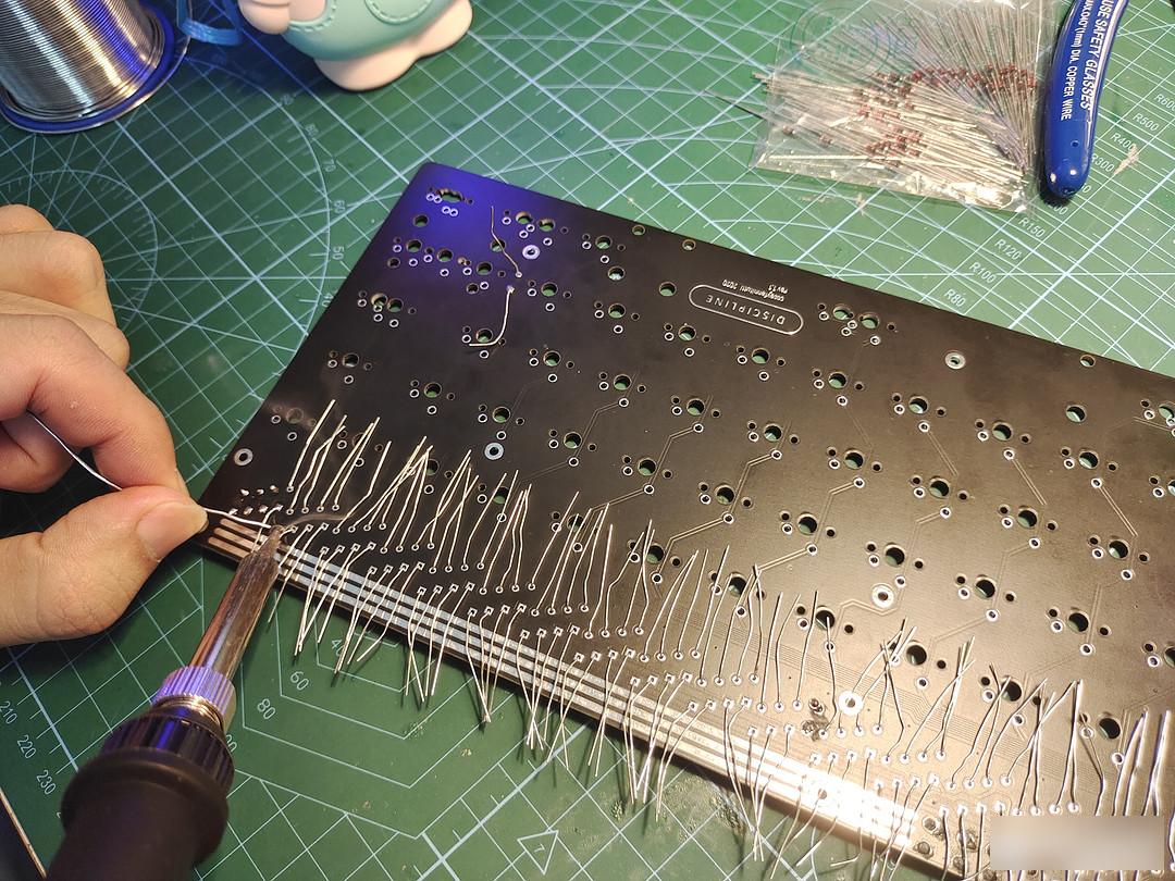
Then there is the diode. It should be noted here that the black of the diode is the negative pole, and the direction is upward. Don't make a mistake. This is a time-consuming and painful process, a total of 69 1N4148, each diode corresponds to a button, and two 1N4729
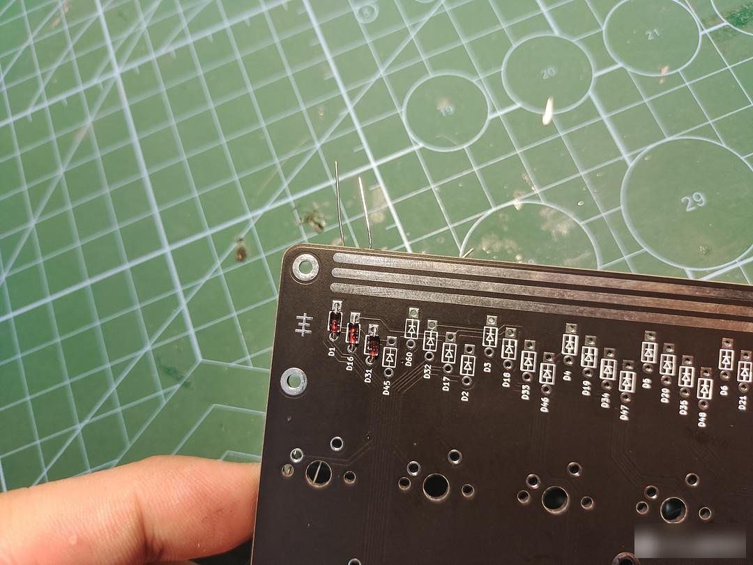

Also forget there is a diode here
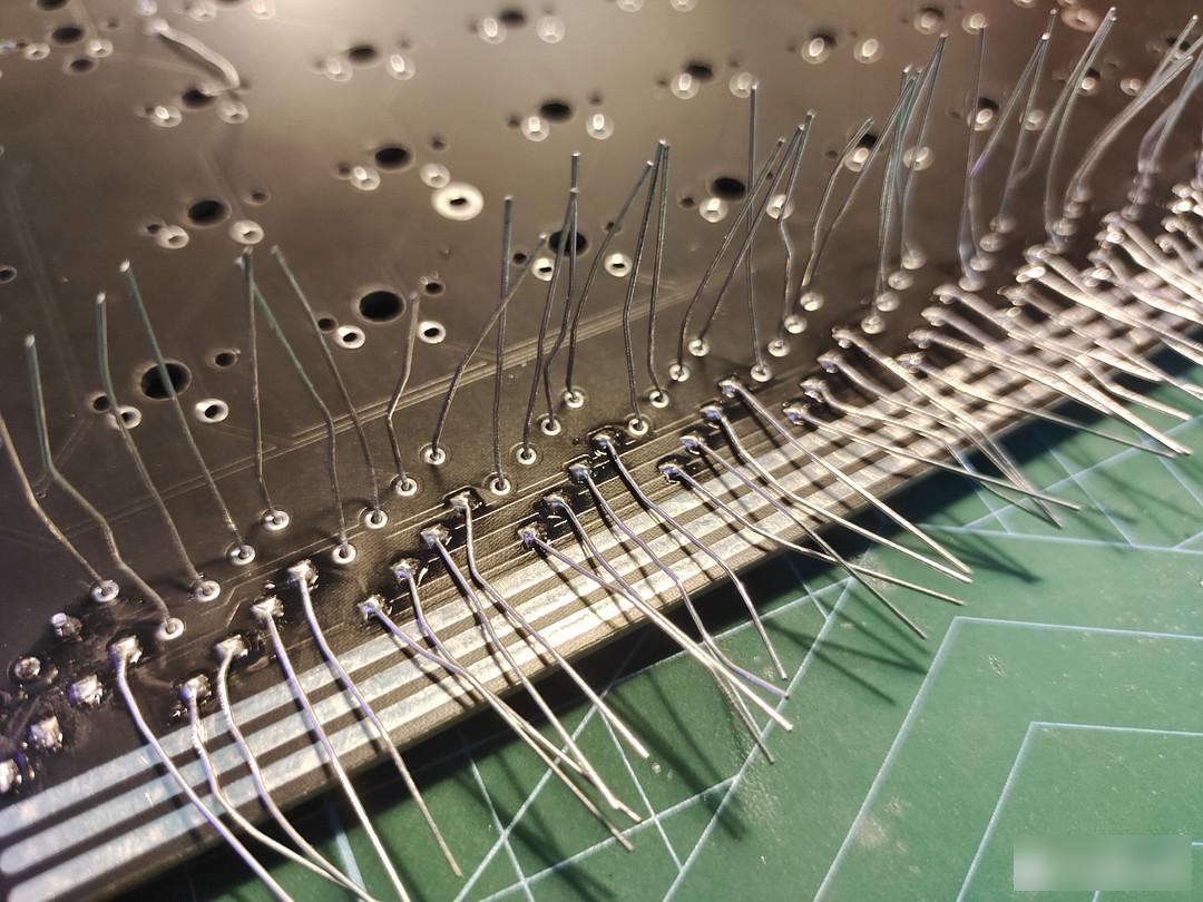
Both pins are bent, and after one end is soldered, pull the other end upright, so that after soldering, you will see round tin spots on the front, which looks better

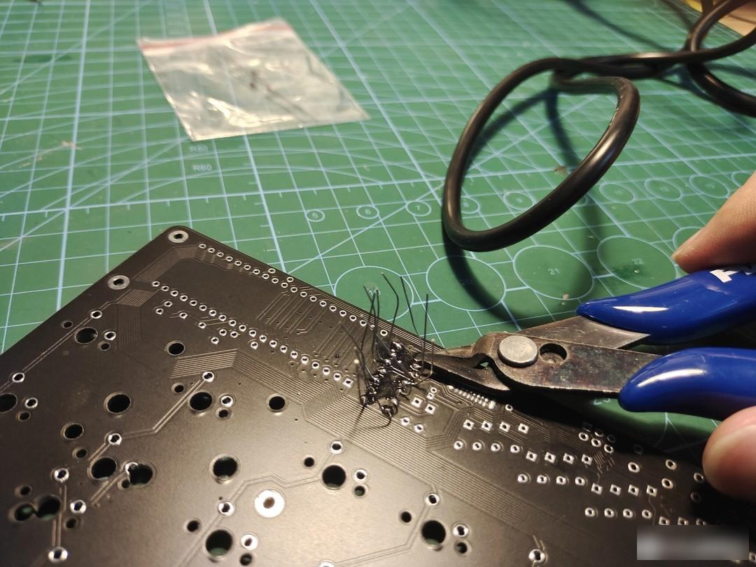
Then there is the process of cutting stitches. There are a lot of cuts, and the process is actually quite decompressed.

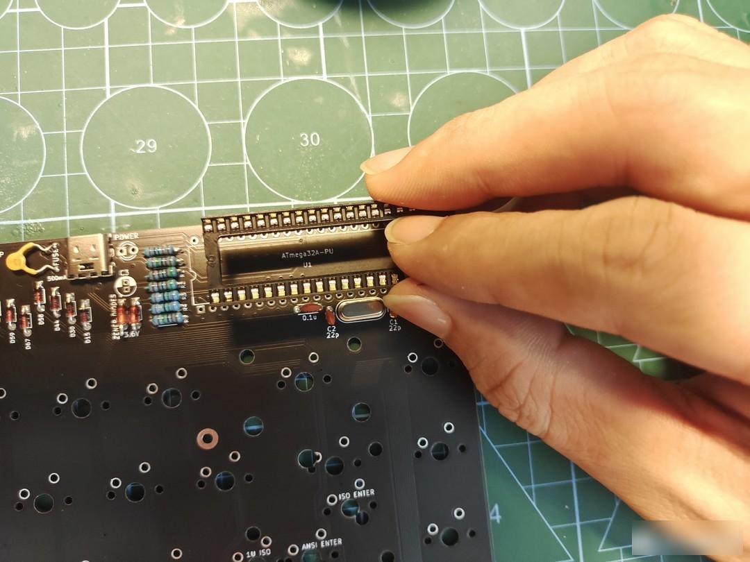
Finally, the main control is started. The main control used by disciphline is ATMEGA32A, 40 pins. It is best to solder a socket on the main control first, so that even if the main control is reversed, it is easy to remove and reconnect. The main control direction should follow the groove marked on the PCB. PS: I forgot to mention the light-emitting diode capacitor, the long leg is the positive pole, just plug it in to the motherboard logo and solder it.

After all components are soldered, everything is ready to start programming. Flash the bootloader first, and only with the bootloader can you flash the keyboard firmware. Flashing the bootloader and burning the firmware requires a USB ISP downloader, and the PCB is a 6PIN interface. When purchasing, remember to search for 51AVR programmer USBASP downloader without shell + adapter board.
Align the GND interface, plug in the ISP downloader, the driver installation process will not be described in detail, the computer is connected to the device manager and the USBasp is connected successfully

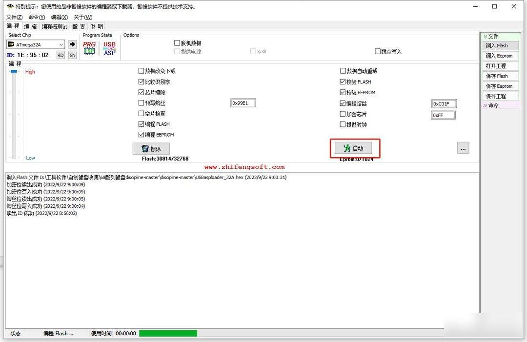
Open the Progisp_1.72 programming software, follow the steps in the figure, select the main control, check the options, set the fuse bit, write and read to see if it is normal
Finally, click to transfer to flash and select bootloader, and then click Automatic to flash into the bootloader.


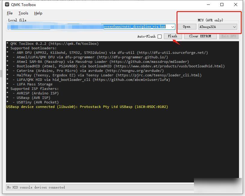
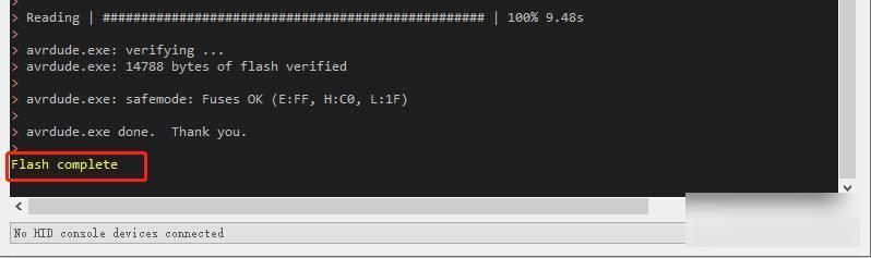
After completion, there is no need to pull out the USBASP downloader, open qmk_toolbox to burn in the keyboard firmware, prompting Flash complete means that the firmware has been written successfully
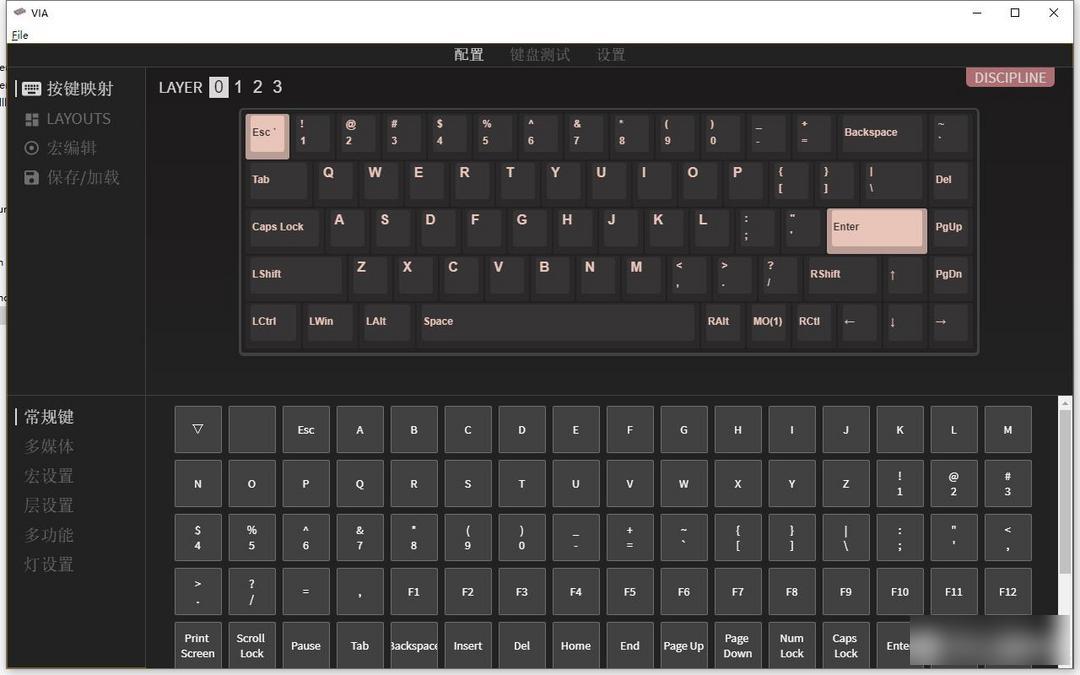
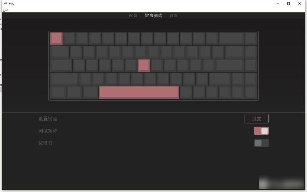
Open VIA to see if it can be recognized. If it is recognized, everything is normal. Use tweezers to simply test whether each button is triggered normally, and then the axis can be turned on.

I use the gray wood switch V3, a linear switch body with 6 hairs. Now, the feel is cost-effective in all aspects, and it is worth recommending. The keyboard uses PCB satellite switches, and the adjustment process of the large keys is omitted. Acrylic shell and acrylic positioning board, the typing sound is very nice, I have a chance to make a video to show it.
After putting on the keycaps, the entire keyboard is complete. I just installed a set of black OEM keyboards. It will look better with XDA or SA keycaps when taking pictures. When I come back from cutting a new shell, I will match it with a set of nice keycaps and take some pictures. This time it is a production process, and I will give you a reference.
Disciphline 65% directly displays the core parts of the PCB at a glance. The popular electronic style in the 90s looks full of retro charm. The diodes are neatly arranged together, very rough and beautiful. All components are plug-in design, just like the feeling of soldering the radio before, it looks more complicated, but in fact the plug-in type is simpler than the patch type, even a novice can easily solder. What a wonderful and profound experience it is to solder a keyboard of your own.
Factory Adress: No.11,FengpingRoad