DIY free combination keyboard: 16, 32, 48, 64 keys [ATmega32A]
Some time ago, I made a 40-key "simplest programmable in-line keyboard with RGB". There are cheaper plans, and this time brings a new one.
The circuit diagram is as follows, directly designed and drawn on JLC online, the circuit structure is relatively simple.
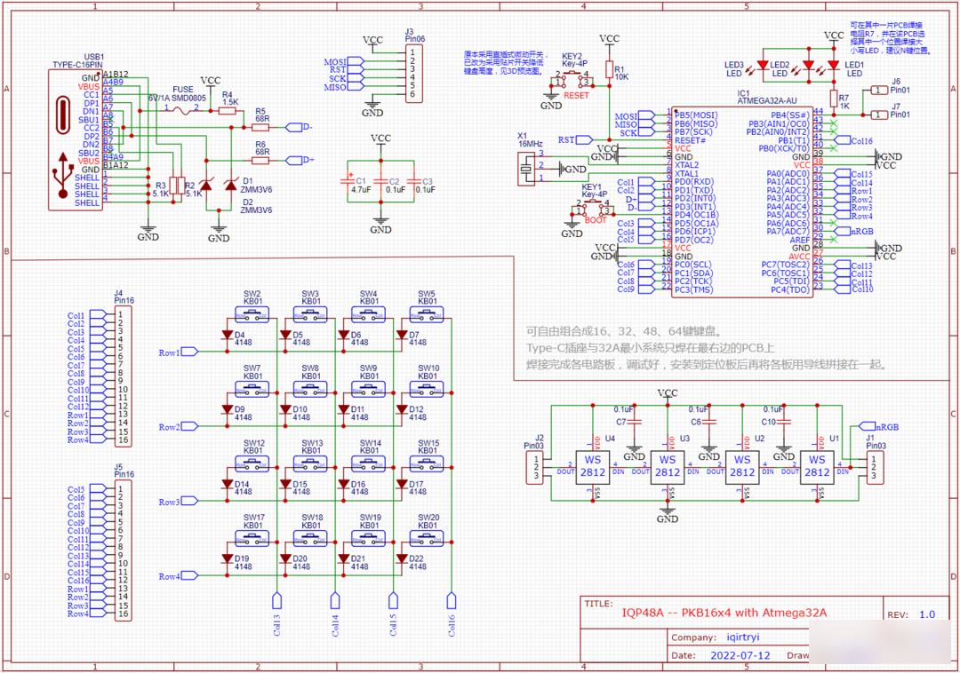
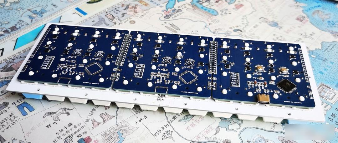
This project uses the relatively cheap Atmega32a chip as the onboard main control. The single PCB has 16 keys, and the same circuit board can be spliced left and right to form an in-line keyboard with 32 keys, 48 keys or 64 keys. Among them, the main control and the type C port are welded on the rightmost PCB.
A must-read for getting started! ! ! A must-read for getting started! ! ! A must-read for getting started! ! ! For the specific production process, please refer to the original project: "The simplest programmable in-line keyboard with RGB"
Production order:
The keyboard is made of 3 pieces of the same PCB spliced from left to right, and the size of the PCB meets the requirements of JLC for free boarding.
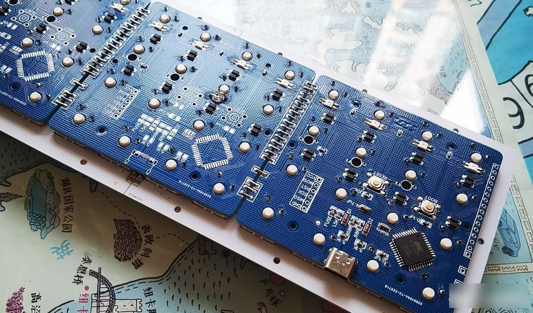
Weld all components except the key shaft;
Mainboard burning BL, firmware, debugging;
The key shaft is stuck on the positioning board, inserted into the PCB, and the two adjacent circuit boards are spliced together by wire welding;
Test whether each key is working properly;
Weld all key shafts;
Shell installation.
Precautions for welding installation:

The soldering of Type C and 32a chip is a bit difficult for Xiaobai. It is recommended to use a heating table and solder paste to complete it, which is much more convenient than an electric soldering iron. Except for the key shaft and individual components, basically everything can be done with a heating table. Solder this kind of small board, apply solder paste to all SMD component pads, put the components except C port and 32a chip, heat, wait for the solder paste of C port and 32a chip to melt, scratch with a sharp object if there is tin Turn it on, then place the chip and C port accurately, press and hold for a few seconds, and solder all the patches at one time, 100% successful, fast and good! Those who are inexperienced can search for related content at station B to learn, and pay attention not to solder too long to avoid damage to components. The heating table shown in the picture above is from a treasure, DIY a PCB heat insulation bracket, simple and practical.

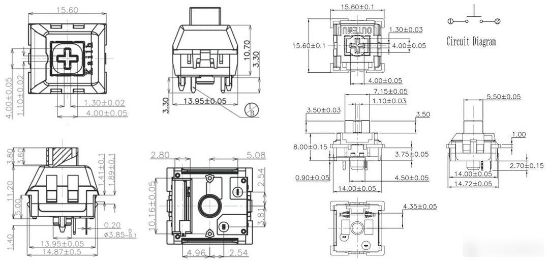
The upper and lower case LED lights can be soldered to any position of any PCB, and the resistor R7 is welded on the PCB. Other boards do not need to solder the upper and lower case lights and R7. The welding method is as shown in the figure above. Don't ask me why I use in-line components, it's because I still have a lot, such as self-modification using SMD packaging. The key shaft adopts the high-tech standard shaft, which is directly welded. If you want to use hot swap, you only need to simply modify the hole size of the pad in the sleeve method. The shaft seat method is not recommended, and the change is large, and the position around the chip is small. . Just use wires to weld the two PCBs together (note the order of production).
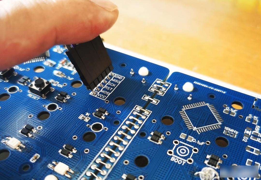
ATmega32a and other master controllers without USB interface, before burning the firmware, you must first use the USBasp burner to burn the bootloader, and then burn the firmware.
The USBasp interface does not require soldering pins or sockets. It is best if there are burning pins when burning the bootloader. If not, insert a common pin on the Dupont cable, then insert it obliquely into the PCB jack, and press lightly when burning. Anyway, it only needs to be burned once.
BOOT and RESET use light touch switches, and there are small holes corresponding to the position of the bottom plate, which is convenient for burning firmware during debugging. If you don't need to debug repeatedly, you don't need to solder the switch, just use tweezers to short it if necessary.

There are two designs of positioning plate and bottom plate for choice: it can be made by whole plate, which saves trouble; it can also be divided into two pieces, which is the choice of JP xx.
The thickness of the frame is determined according to the actual measurement of the selected key shaft and the height of the circuit board and components. The key shaft is divided into standard key shaft and short key.
After receiving the positioning board, bottom plate and frame, if necessary, fix them with copper pillars and screws first, and then sand them smooth with coarse, medium and fine sandpaper in turn. Do not polish the circuit board and key shaft after installing, otherwise the dust will enter the key shaft and affect the feel and quality.
Burn bootloader, firmware:
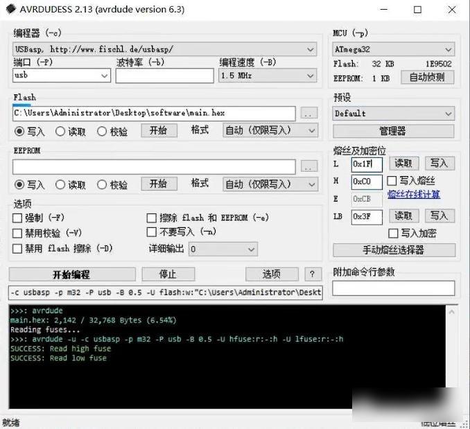
1. The USBasp programmer burns into the bootloader. When burning, pay attention to the fuse bit as shown in the figure above. A brief summary of the steps is: initialization (select programmer, select bl file) - read - modify L, H - write - read - start programming, the bootloader only needs to be successfully burned once. Station B has a very detailed video explanation.
2. There is a compiled hex firmware file in the attachment, which can be burned directly.
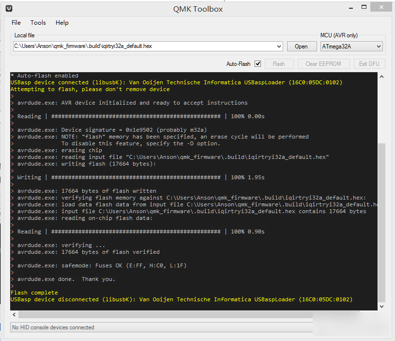
The generated hex file is burnt into the module with qmk toolbox software, the steps are as follows:
Open the hex file.
Select the MCU as ATmega32a.
Click Auto-Flash
Press and hold the boot switch, and then press the reset switch. If the circuit board is soldered correctly, the programming will start. Wait for a few seconds to complete, and release the boot.
Press the reset switch again, and the RGB lights of different colors on the bottom row of the keyboard will light up. Congratulations, the keyboard can be used normally.
Complete the assembly:
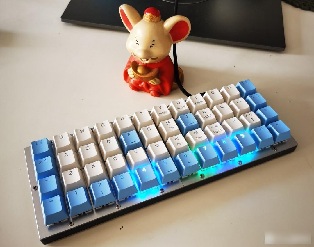
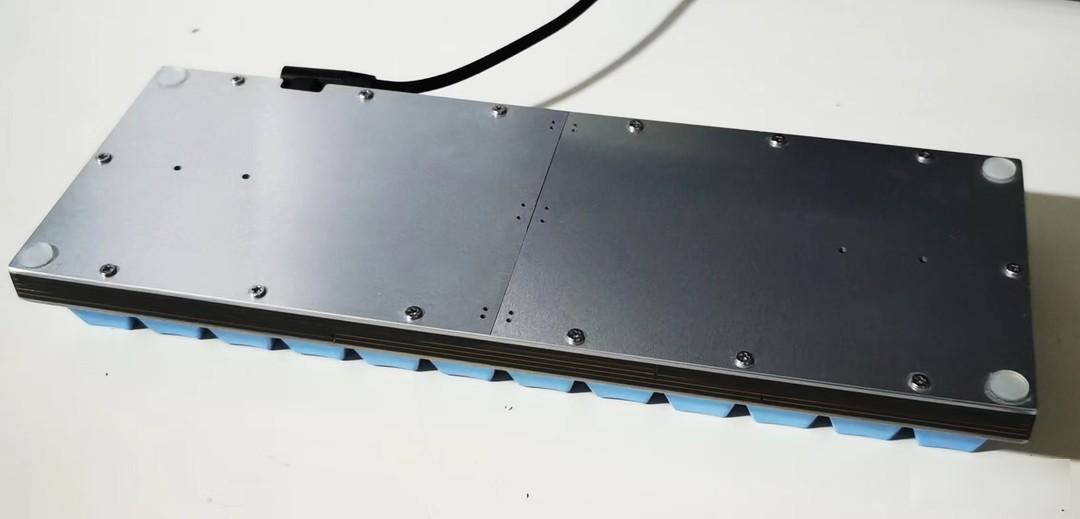
This is the final product, with a 9.9 yuan free shipping keycap, which is cheap, simple and easy to use. The bottom row of the keyboard is equipped with WS2812 RGB lights, and different colors correspond to different layers. Don't tell people, my aluminum positioning plate and bottom plate are from the next door neighbor JP's for free.
Keyboard arrangement design:
I always think that the key setting is the soul of the whole keyboard DIY. If you set it according to your needs, the small keyboard will be very convenient and efficient to use.
1. 16-key numeric keypad
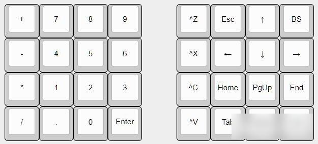
The left is layer 0, and when the left thumb presses the Enter key, it enters the layer shown on the right. Other layers can modify their definitions as needed.
2. 32-key auxiliary keyboard
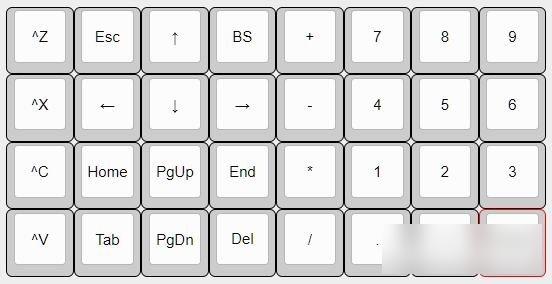
This auxiliary keyboard is especially suitable for right-handed mouse operation and left-handed single-handed operation. Other layers can be modified and defined by themselves according to needs.
3. 48-key full-function keyboard
The keybindings have undergone several changes:
In the first version, all punctuation marks are uniformly placed on the first floor, and the right-hand numeric keypad.
In the second version, it is changed to a left-handed numeric keypad and a right-handed direction key, which is more convenient for the left hand to input numbers with one hand.
In the third version, as shown in the scheme below, frequently used independent shortcut keys for copy and paste are added to the leftmost column, and media playback or other common shortcut keys are added to the rightmost column. The F area is changed to the middle of the 3rd floor, which is convenient for left-handed one-handed operation.
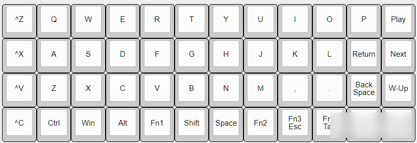
Layer 0: letters + function keys, long press Fn1 to enter the number and punctuation layer, Fn2 to enter the arrow keys and punctuation layer, Fn3 for the F function area, virtual mouse, Fn4 for software shortcut keys and media keys.
Press Fn1 and space to switch Chinese. When inputting Chinese, press the space with the right thumb to select the first word, press Shift with the left thumb to select the second word, and press Shift with the left thumb to input capital letters. All operations do not need to leave the main area.
Compared with the previous 40 keys, the biggest change of this project is: the leftmost is the frequently used copy and paste independent shortcut key, and the far right is the independent direction key.
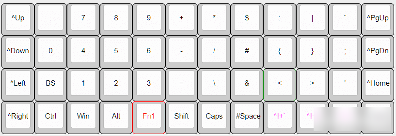
Layer 1: The left side is the numeric keyboard, and the right side is part of the punctuation marks. All punctuation marks are arranged according to personal habits and easy to remember, such as ? It is the F position where Fa asks the question, # is at the J position of the number sign, ~curve q, @at, [bracket Z, {curly bracket K, Na N, $Us knife, "double quotation mark S, ... +-× /= Taking into account the use of the numeric keypad. When I started using this solution, it took a long time for my left hand to get used to it, but it is still worth it.

Layer 2: Leftover punctuation marks on the left, arrow keys on the right. Now put both hands on the keyboard, press Fn1 with the left thumb naturally, and feel that there is a numeric keypad underneath, and press Fn2 with the right finger, and feel that there is a directional keyboard underneath, which is very natural and comfortable. Finally, when I used it myself, the rightmost column of independent arrow keys was changed to PLAY, NEXT, and two commonly used software shortcut keys.

Level 3: Still the spare shortcut keys, F area, and virtual mouse. Press and hold Fn3 below with the left thumb, and then press the buttons in the middle 4 rows. I found that it is very easy to operate the keys in the F area with one hand.
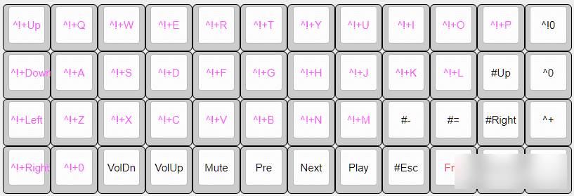
The 4th floor arranges media playback keys and shortcut keys for commonly used software. For example, Fn4+C runs Chrome, Fn4+Q runs QQ, Fn4+W runs WeChat, Fn4+M runs music software, Fn4+V runs video software...
4. 64-key full-featured keyboard, including a left-hand independent numeric keypad.

On the basis of the above 48-key full-function keyboard, an independent left-hand numeric keyboard is added, which is suitable for the recognition and use of a large number of input numbers. Other layers are consistent with 48 keys.
The above key settings are more designed according to the operation of the left-handed keyboard and the right-handed mouse, and the numbers, F area, and direction keys are all suitable for one-handed operation. All shortcut keys only need to be pressed at the same time, and a lot of space is reserved Shortcut keys for setting.
Why is it cheap?
The relatively low-cost ATmega32A chip is used as the onboard master control;
The minimalist 48-key design minimizes the cost of key shafts;
The splicing circuit board mode is adopted, and the size of each circuit board meets the free requirement;
All 1U buttons are used, and the keycaps are simple and cheap, and there is no need to buy satellite switches;
Simple structure, small shell.
How easy to use?
Well-designed small configuration, all buttons are within the comfortable operating range of ten fingers, and the little finger does not need to press outwards;
The most frequently used enter key and backspace key are under the little finger of the right hand, which can be operated without moving;
The button to switch between the 1st and 2nd floors and the shift and space bar are just below the two thumbs. The function of the thumb is no longer only used to press the space, and the utilization rate of the ten fingers is effectively improved;
Press the Fn1 key with the left thumb, and under the left hand is a complete numeric keypad and arithmetic symbols, which is very suitable for left-handed numbers and right-handed mouse operations;
Press the Fn2 key with the thumb of the right hand, and under the right hand are up, down, left, right, Home, End and other direction keys. The gesture is similar to holding a mouse, which is natural and comfortable. It is especially convenient to move the cursor position when coding;
For all punctuation marks, you only need to press the Fn1 or Fn2 key with your thumb, and press the corresponding key with the finger of the other hand. All the keys are in the comfort zone of your fingers;
Press the Fn3 key with the left thumb, press the F key with one hand is easy to use, the right hand Fn3 key, the virtual mouse...
Of course, compared with the large-arranged keyboard, the small keyboard must be learned and proficient by oneself, and it will be convenient and efficient after the formation of muscle memory. The key setting is also getting more and more perfect in my continuous use.
Attached are the verified firmware .hex files, and the QMK source code. iqirtryi32a_iqp32a.hex is the 16-key and 32-key firmware, iqirtryi32a_iqp64a.hex is the 48-key and 64-key firmware, zip is the corresponding source code.
During the production process, I referred to a lot of information on the Internet, and thank you again for your contributions!
Thanks to Yomen's open source project, the bl file USBasploader_32A.hex comes from his open source. Without his open source project and detailed explanation on station B, this project would not be so simple and smooth, thank you!
Thank you for your attention, if you find it interesting, remember to like + comment + bookmark!
Factory Adress: No.11,FengpingRoad