The simplest programmable inline keyboard with RGB, suitable for beginners [Pro Micro]
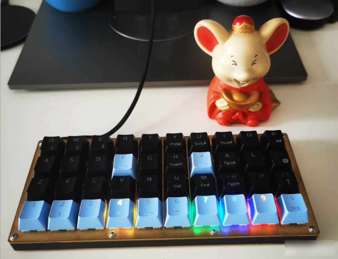
This keyboard has a minimalist design and is easy to make. The first choice for beginners: Pro Micro module is used as the main control, the circuit is mature and simple; the in-line design is adopted, all 1U keys are used, the keycaps are simple and cheap, and there is no need to buy satellite switches; the structure is simple , the shell is compact; it is equipped with RGB display layer status, which is convenient and easy to use; carefully and uniquely designed with small column keys, the function keys such as Ctrl, Win, Alt are all arranged in the bottom row, and there is an independent Del key, all keys are in the ten fingers comfort zone; 40-key design, no more, no less, no more , the best choice for simplicity and portability.
How to make the small configuration keyboard easy to use?
Well-designed small configuration, all buttons are within the comfortable operating range of ten fingers, and the little finger does not need to press outwards;
The most frequently used enter key and backspace key are under the little finger of the right hand, which can be operated without moving;
The button to switch between the 1st and 2nd floors and the shift and space bar are just below the two thumbs. The function of the thumb is no longer only used to press the space, and the utilization rate of the ten fingers is effectively improved;
Press the Fn1 key with the thumb of the left hand, and there is a complete numeric keypad and arithmetic symbols under the left hand, which is very suitable for left-handed numbers and right-handed mouse operations; [see new version]
Press the Fn2 key with the thumb of the right hand, and under the right hand are up, down, left, right, Home, End and other direction keys. The gesture is similar to holding a mouse, which is natural and comfortable. It is especially convenient to move the cursor position when coding; [see new version]
For all punctuation marks, you only need to press the Fn1 or Fn2 key with your thumb, and press the corresponding key with the finger of the other hand. All the keys are in the comfort zone of your fingers;
Press the Fn3 key with the left thumb, press the F key with one hand is easy to use, the right hand Fn3 key, the virtual mouse... [see new version]
The following production process is suitable for reading for the first time, masters please skip it.
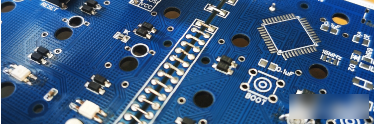
The Pro Micro module is a complete small system with the ATmega32U4 single-chip microcomputer as the core. It has a mini usb socket and can be used to simulate HID equipment and make a keyboard. It only needs to add a small number of components to complete it; the ATmega32U4 main control comes with a USB interface, no The burner burns firmware, which is perfectly supported by QMK official, and can generate firmware online. You can make a full-key programmable keyboard without in-depth programming yourself.
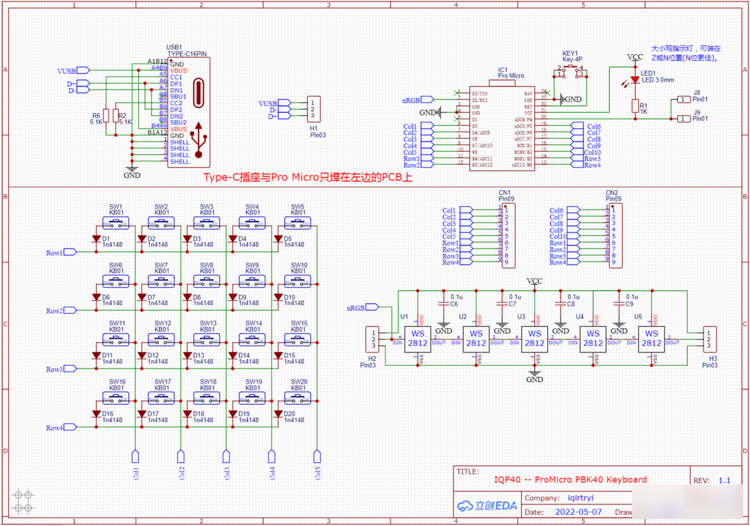
The circuit diagram of the Pro Micro as the main control is as above, and the bottom row of the keyboard is equipped with WS2812 RGB lights, and different colors correspond to different layers.
Different keyboards can be made according to requirements:
1. It can be made into a 20-key auxiliary keyboard, see 20-key keypad, your right-hand man:

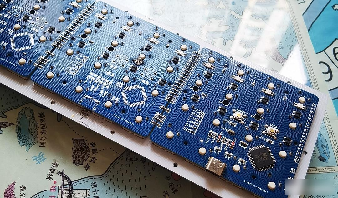
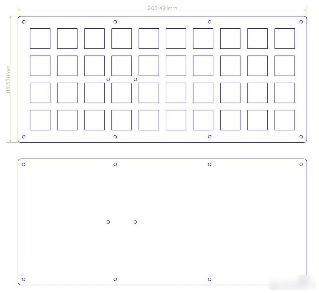
2. In this project, the same circuit board is spliced left and right to form a 40-key in-line keyboard. The main control and type C port are welded on the left PCB.

3. 48-key in-line keyboard with independent copy, cut, and paste keys to assist editing work:

4. 40% programmable conventional keyboard, no need to change your typing habits too much:
1. Must-read for beginners! ! ! A must-read for getting started! ! ! A must-read for getting started! ! !
The important thing is said three times. If you want to successfully complete your first self-made keyboard, it is recommended to read the relevant information carefully.
2. Make circuit boards, purchase components, and solder
The production sequence is as follows:
1. Weld all components except the key shaft;
2. The motherboard burns BL, firmware, and debugs;
3. The key shaft is stuck on the positioning board, inserted into the PCB, and the two adjacent circuit boards are spliced together by wire welding;
4. Test whether each button works normally;
5. Weld all key shafts;
6. Shell installation.
Use the PCB file of this project to place an order directly at JLC to make the board, and the size meets the free conditions.

For components, please refer to the BOM list and circuit diagram, and the circuit diagram shall prevail. For component packaging, please refer to the 3D preview of the PCB.
Note: The pictures in this article are for reference, some of them may not be the pictures of this project.
First of all, solder all the SMD components, pay attention not to make mistakes in the components, some components are directional, and ensure that each solder joint has no false soldering or short circuit, so that there is no need to spend a lot of time troubleshooting in the later stage. Soldering Type C and some chips with dense pins is a bit difficult for Xiaobai, and soldering with a soldering iron often fails or even causes damage. It is strongly recommended to use a heating table and solder paste to complete it, which is much more convenient and easy to use than an electric soldering iron. Except for the key shaft and individual components, basically everything can be done with a heating table. Solder this kind of small board, apply solder paste to all SMD component pads, put the components except C port and chip, heat, wait for the solder paste of C port and chip to melt, and use a sharp object to cut off the tinned parts. Then put the chip and C port accurately, press and hold for a few seconds, and solder all the patches at one time, 100% successful, fast and good! Those who are inexperienced can search for relevant content on station B to learn. Note that only a thin layer of solder paste for the C port and the chip is required. The total soldering time should not be too long to avoid damage to the components. The heating table shown in the picture above is from a treasure, DIY a PCB heat insulation bracket, simple and practical.
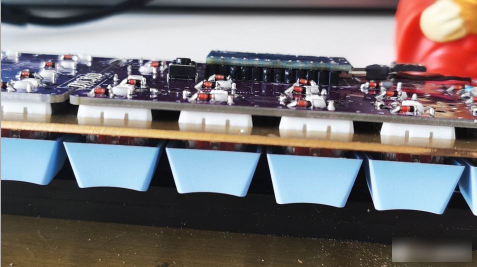

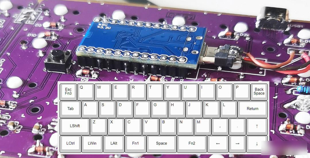
Then solder in-line components, such as modules, micro switches, etc. The round plug female is welded on the main board, the welding hole is enlarged, and the round plug female is attached to the main board. The components of the PRO MICRO module face the main board. The module does not use pins, but directly solders the component pins as pins to minimize the height. (The purple circuit board is the first board I soldered with an old pointed soldering iron that has been dusty for many years. Please ignore its craftsmanship)
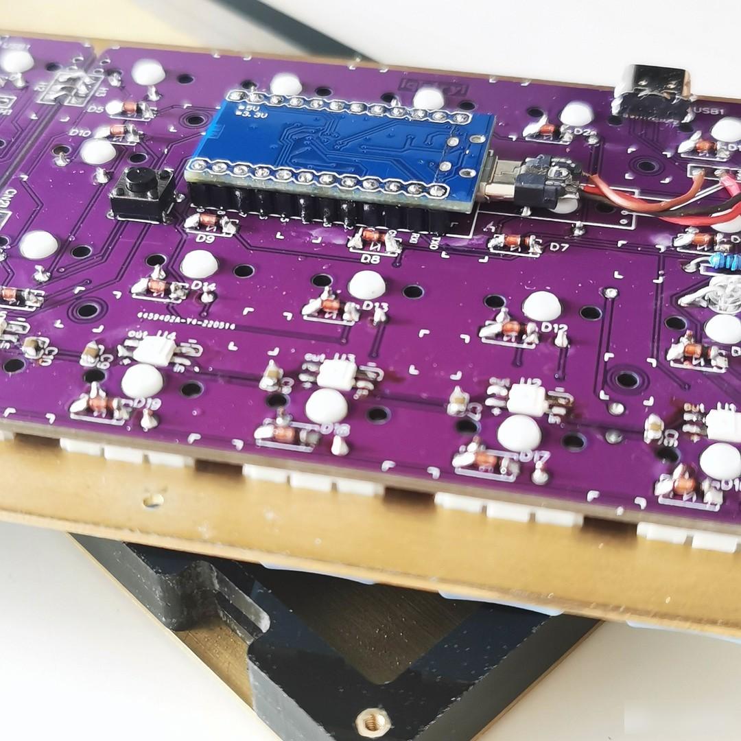
The module itself comes with a micro socket, insert the micro plug, and connect the module to the motherboard with a wire.
The reset uses a micro switch, and a small hole is opened at the position of the bottom plate, which is convenient for burning the firmware. If you don't need to debug repeatedly, you don't need to solder the switch, just use tweezers to short it if necessary.
At this time, first burn the firmware according to the instructions described later, and then do the next step of welding after debugging the motherboard.
Snap the key shaft to the positioning plate, insert it into the circuit board, and solder it with wires as shown in the picture above.
Then test whether each key is working properly.
Finally, solder on all the key shafts.
Soldering done!
3. Customized keyboard shell
There are many kinds of keyboard structures, and you can search and refer to online materials.
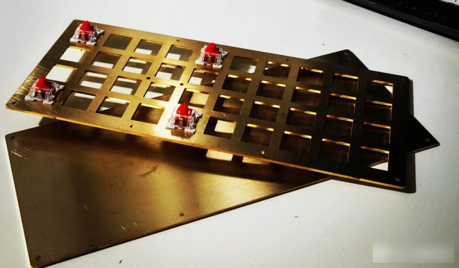
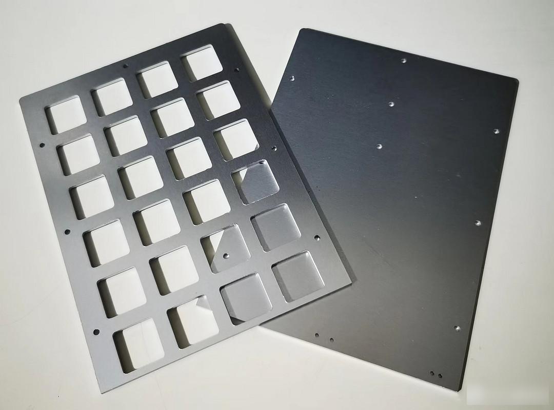
Methods include 3D printing, acrylic cutting, aluminum CNC, etc. This project adopts the simplest structure: positioning plate + frame + bottom plate are stacked up and down in sequence. The positioning plate can be made of acrylic, copper, aluminum and other materials, and the frame can be made of acrylic, PC, etc. Choose according to personal preference.
I like the heavy feeling of brass, so I chose copper fixing and copper bottom. If you consider portability, price, and rich colors, it is recommended to use acrylic together with the middle frame.
Of course, the aluminum substrate positioning board with split design is also a good choice to save money, and is loved by many diyers.
The project includes design drawings of positioning boards, frames, and bottom plates, which can be directly exported to dxf files and handed over to the manufacturer for customization. The quantity and thickness should be indicated when customizing. The thickness of the positioning plate is 1.5mm. If it is too thick or too thin, it will not be able to hold the key shaft well. Note that the thickness of the frame should be determined according to the actual measurement of the selected key shaft and the height of the circuit board and components.
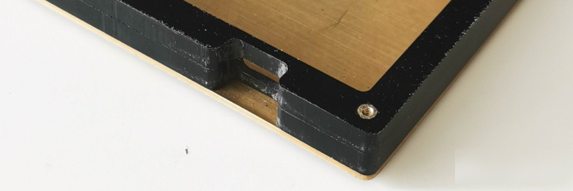
Considering the convenience and cost of production, one or two frames can be used according to the position of type C. If the C port of this project is in the horizontal center position, two identical frames should be used and processed by hand with a file; if the C port is tight To attach the bottom plate, only one frame is needed. If you don't want to process it by hand, you can customize one more frame with a C-port outlet, see the design drawing.
When installing, use M2.0 round copper pillars to penetrate the frame, and fix both ends with M2.0 screws. Measure and determine the length of copper pillars and screws.
It is recommended to fix the positioning board, frame, and bottom plate before installing the circuit board, and then sand the surrounding area of the keyboard with coarse, medium, and fine sandpaper in turn. Otherwise, the key shaft and keycap will be dirty after all is installed and then polished.
4. Key design
According to your own usage habits, design the layers of the keyboard and the keys of each layer, and constantly adjust to the best during use.
The following is the key setting of version V1.0. After continuous use, it has entered the update of version 2.0, which is more efficient and easier to use. For the new version, please refer to the web page:
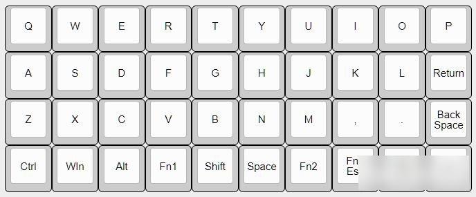
Layer 0: letters + function keys, Fn1 enters the punctuation layer, Fn2 enters the number layer, Fn3 is the F function area, virtual mouse, and arrow keys, and Fn4 is the software shortcut key and media key.
Press Fn1 and space to switch Chinese. When inputting Chinese, press space with your thumb to select the first word, Shift to select the second word, and press Shift with your left thumb to input capital letters. All operations do not need to leave the main area.
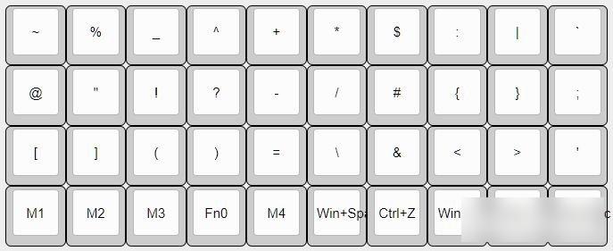
Layer 1: All punctuation marks are arranged according to personal habits and easy to remember, such as ? It is the F position where Fa asks the question, # is at the J position of the number sign, ~curve q, @at, [bracket Z, {curly bracket K, Na N, $Us knife, "double quotation mark S, ... +-× /= Take into account the use of the numeric keypad.
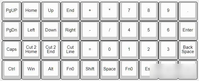
Layer 2: The right side is a complete numeric keypad, and double-clicking Fn2 can also lock layer 2, which is convenient for inputting a large number of numbers. On the left is the arrow key, which is convenient for text editing, and there is no need to move your hands when using it.

Layer 3: Press the right thumb on Fn3, just like the gesture of using a mouse, which is convenient and comfortable.
Compared with the conventional keyboard, the biggest advantage of the inline keyboard is that the layout of the arrow keys and numeric keypad is very neat and easy to use. For playing games, you can also set up a special layer.
Although the keyboard is small, it has complete functions, and Xiaobai can also enjoy the fun of DIY.
The key setting is the soul of the whole keyboard. If you set it according to your needs, it will be very convenient to use. It will soon become my only main keyboard.
5. Generate firmware and burn firmware
The keyboard firmware file using ATmega32U4 as the main control can be directly made on the website, no programming knowledge is required, it is simple and fast, and the hex firmware file and source code can be exported.
If you need more functions, such as RGB display, you need to rewrite the source code a little, and install the QMK MSYS software to compile and generate hex files.
(Note: If you use ATmega32a and other master controllers without USB interface, you must use a programmer to burn the bootloader before burning the firmware, and then follow the steps below to burn the firmware. Please refer to the instructions for the method of burning the bootloader. )
There is a compiled hex firmware file in the attachment, which can be burned directly.
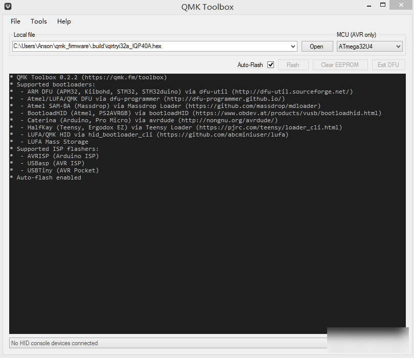
The generated hex file is burnt into the module with qmk toolbox software, the steps are as follows:
1. Open the hex file.
2. Select MCU as ATmega32U4.
3. Click Auto-Flash
4. Press the reset micro switch.
If the soldering of the circuit board is correct, wait for a few seconds, and the firmware burning is completed. At this time, several RGB lights of different colors on the bottom row of the keyboard light up. Congratulations, the keyboard can be used normally.

If you need to change the keyboard settings on the existing basis, the attachment also provides the QMK source code of this project, follow the steps below:
1. Download and install the QMK MSYS software, please read carefully the installation and usage methods:
2. Copy the folder after decompressing the attached source code (such as iqp64a) to the installation path of QMK MSYS, such as C:Usersiqirtryiqmk_firmwarekeyboardsiqp64a
3. Use any text editor software to modify the keymap.c file. When modifying, the format remains the same, just change the arrangement of each key. For the code meaning of each key, please refer to the key setting diagram of this project. For more details, please read the official qmk document.
4. Compile and generate hex files with QMK MSYS software.
Main components purchase link:
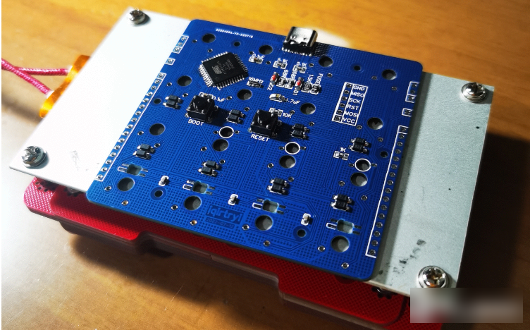
If you need to reduce the height of the keyboard and reduce the cost, you can choose a slightly more complicated 40-key chip solution:
If you use copy and paste shortcut keys frequently, you can use 48 and 64 key chip solutions:

Thank you for your attention, if you find it interesting, remember to like + comment + bookmark!
Factory Adress: No.11,FengpingRoad